|
|
Project! Touch Activated Alarm成功了!有Propasal在里面..可以参考
[复制链接]
|
|
|
 发表于 17-4-2007 06:29 PM
|
显示全部楼层
发表于 17-4-2007 06:29 PM
|
显示全部楼层
3. 文章里面写..如果我的!Power source 9volts capacitor 至少要18volts,我买了 capacitor 16 volts 那么我的power source是不是要 8 volts??? 6 volt可以用吗?
--Power source 9volts , capacitor = 18V 我认为没问题。
如果 capacitor 的用途是做 timing, 那么 capacitor 越接近 power source voltage 越好 (尤其是 e-cap)。 |
|
|
|
|
|
|
|
|
|
|
|

楼主 |
发表于 17-4-2007 09:48 PM
|
显示全部楼层
原帖由 GeMan 于 17-4-2007 06:29 PM 发表
3. 文章里面写..如果我的!Power source 9volts capacitor 至少要18volts,我买了 capacitor 16 volts 那么我的power source是不是要 8 volts??? 6 volt可以用吗?
--Power source 9volts , capacitor = ...
18volt 的capitor 10nF 的找不到啊...在下来是25volt.
我买的16volt...那么我是不是至少要用8 volt power source..?? |
|
|
|
|
|
|
|
|
|
|
|
楼主 |
发表于 18-4-2007 08:34 PM
|
显示全部楼层
不用烦了...做到了......
1.只是trigger不是很stable...时能sense..时不能.....
2.在battery 那边加了suis...但不能用...不知道作么???
[ 本帖最后由 音魂不散 于 19-4-2007 01:09 PM 编辑 ] |
|
|
|
|
|
|
|
|
|
|
|
发表于 19-4-2007 02:03 PM
|
显示全部楼层
1.只是trigger不是很stable...时能sense..时不能.....
接pin2的电线长度会影响的。
2.在battery 那边加了suis...但不能用...不知道作么???
Switch 是很简单直接的,不可以用是99%你接错了,1%是新买的switch坏了。 |
|
|
|
|
|
|
|
|
|
|
|
楼主 |
发表于 19-4-2007 05:30 PM
|
显示全部楼层
原帖由 pic 于 19-4-2007 02:03 PM 发表
接pin2的电线长度会影响的。
Switch 是很简单直接的,不可以用是99%你接错了,1%是新买的switch坏了。
明白了...原来suis.....接suis....一开..并没有pulse..
所以我以为suis 不能用...但其实,trigger还可以...
至于pin2 的...可能是wayar肮脏了..换了就可以了....
大大,relay那边我接了LED+BUZZER+3V BAtery....
buzzer 声不是很响...我想用9V...不知道..LED会烧掉吗???
[ 本帖最后由 音魂不散 于 20-4-2007 08:44 AM 编辑 ] |
|
|
|
|
|
|
|
|
|
|
|
发表于 20-4-2007 10:16 AM
|
显示全部楼层
明白了...原来suis.....接suis....一开..并没有pulse..
所以我以为suis 不能用...但其实,trigger还可以...
到我不明白。。。
至于pin2 的...可能是wayar肮脏了..换了就可以了....
是这样的吗?
大大,relay那边我接了LED+BUZZER+3V BAtery....
buzzer 声不是很响...我想用9V...不知道..LED会烧掉吗???
LED怕烧掉就要加330ohm~680ohm的电阻。 |
|
|
|
|
|
|
|
|
|
|
|
楼主 |
发表于 20-4-2007 10:30 AM
|
显示全部楼层
|
|
|
|
|
|
|
|
|
|
|
发表于 20-4-2007 12:15 PM
|
显示全部楼层
回复 #67 音魂不散 的帖子
有完整的报告我会格外加分奖励。
只是有一点,看到你那死头像,每看一次,我禁不住很想扁你一次,扣你的分。
不知大家有同感吗? |
|
|
|
|
|
|
|
|
|
|
|
发表于 20-4-2007 08:35 PM
|
显示全部楼层
|
|
|
|
|
|
|
|
|
|
|
楼主 |
发表于 20-4-2007 11:10 PM
|
显示全部楼层
|
|
|
|
|
|
|
|
|
|
|
楼主 |
发表于 21-4-2007 08:05 PM
|
显示全部楼层
我在relay后面加点.....circuit...
这circuit是可以左右LED轮流闪....象这样...

因为我不想只是等而已...所以我尝试加Buzzer...但问题来了..........
[ 本帖最后由 音魂不散 于 21-4-2007 08:31 PM 编辑 ] |
|
|
|
|
|
|
|
|
|
|
|
楼主 |
发表于 21-4-2007 08:31 PM
|
显示全部楼层
Case 1:
这样接发....relay 会跳...但circuit 没function...
我这样接是要LED可以闪之余..buzzer也可以一直响........
Case 2:
我再用pallel排发接...LED可以轮流闪..BUZZER可以响..但是短短续续跟这LED闪而响....
但buzzer 响得蛮小声...
1. 我想Buzzer可以直接响的...不要一声一声的...为什么CASE 1的办法行不通??
是不是9V 不够supply???
2. 如果真的不能一直响的...那么我要在CASE 2,提高BUZZER的声音要怎样做???
[ 本帖最后由 音魂不散 于 21-4-2007 08:38 PM 编辑 ] |
|
|
|
|
|
|
|
|
|
|
|
发表于 23-4-2007 11:51 AM
|
显示全部楼层
|
|
|
|
|
|
|
|
|
|
|
楼主 |
发表于 3-5-2007 04:17 PM
|
显示全部楼层
这边有小弟...project 的propasal..
贡大家参考...
Concept and Requirements Document
Touch Activated Alarm
By --------- Project Goals
Touch activated alarm is a sensitive and reliable alarm. If it is determined that such a device is commercially popularized, the project could then be mass-produced.
Introduction
The proposed touch activated alarm is a simple yet practical project. The proposed touch activated alarm is a practical project. It will enable us to be aware when someone touching the trigger, this device will make a ‘beep-beep’ sound and LED will flash when someone touching the trigger wire. The device is not only interesting to experiment, but it has practical applications as well. As example, the trigger wire can attach on some metal case, when someone touching the case the buzzer will sound. The device is not only interesting to experiment, but it has practical applications as well.
Project Objectives
This project must fulfill the following requirements: inexpensive to produce, reliable, easy to use and attractive. Touch activated alarm will be met in the following ways:
Cost
By designing a simple circuit to minimize the quantities of components used in building circuit the cost will be kept low. It is less than RM 25.
Reliability
By using solid-state active component and printed circuit board construction techniques, a high degree of the reliability will be obtained.
Safety
The project is designed to operate on a low direct current 9V transistor battery. Such a voltage source presents no risk of electrical shock.
Ease of use
With the use on off switch, an alarm can be switch on of switch off easily.
External devices control
By choosing relays with the appropriate number of contacts, suitably rated, practically any external electrical or electronic device such as music circuit can be switch on or off.
Attractive
By using external flashing LED, the circuit is look more attractive.
Project Responsibility
This project is a part of the requirements upon the completion of this course, as it is also a learning experience for the electronics student. Each individual involve in this project is responsible for the design, drawing, experimenting, prototyping, testing, troubleshooting and final documentation phases of the touch activated alarm.
[ 本帖最后由 音魂不散 于 3-5-2007 04:27 PM 编辑 ] |
评分
-
查看全部评分
|
|
|
|
|
|
|
|
|
|
|
楼主 |
发表于 3-5-2007 04:28 PM
|
显示全部楼层
Project Theory of the Operation

Touch activated alarm: Operating voltage = 9 V DC

Circuit Operation:
This circuit is enclosed into a box. The trigger wire is leaving out from the box and attach to any metal part. The trigger wire is connected to pin 2 of the 555 and will trigger the relay, using body resistance when some is touching the metal part. When the relay was trigger it will generate the LED flashing circuit and LED will flash and the buzzer wills a sound. The flashing timing can adjust by trimmer.
Note:
- The working voltage of capacitor is at least double the supplied voltage.
- The surface of metal part must be clean and makes good contact with the trigger wire.
- Make sure the metal casing was not grounded.
Electronics instructor’s approval, Date
_______________________ _____________
[ 本帖最后由 音魂不散 于 4-5-2007 08:49 AM 编辑 ] |
|
|
|
|
|
|
|
|
|
|
|
楼主 |
发表于 3-5-2007 04:53 PM
|
显示全部楼层
|
Test Results Document
Name of Project: Touch Activated Alarm
Person(s) Performing Tests: Lim Poey Chuan
Preliminary Test Results
1. Are all wiring complete and correct? Init. _________
Date _________
2. Are all soldering connections good? Init. _________
Date _________
3. Are all components in the correct location? Init. _________
Date _________
4. Are all components installed in the correct direction? Init. _________
Date _________
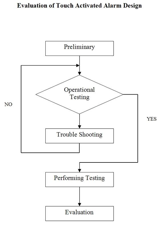
Operational Test Results
1. Any catastrophic failure? Yes ____ No ____ Init. ____________
Explain: _______________________________________________________
_______________________________________________________________
_______________________________________________________________
2. Any minor problems? Yes ____ No ____ Init. ____________
Explain: _______________________________________________________
_______________________________________________________________
_______________________________________________________________
3. Calibration, if necessary. Yes ____ No ____ Init. ____________
Explain: ________________________________________________________
_______________________________________________________________
_______________________________________________________________
4. Is troubleshooting required? Yes ____ No ____ Init. ____________
What is anticipated? ______________________________________________
_______________________________________________________________
_______________________________________________________________
5. Is project operation satisfactory at this time?
Yes ____ No ____ Init. _____ Date _______
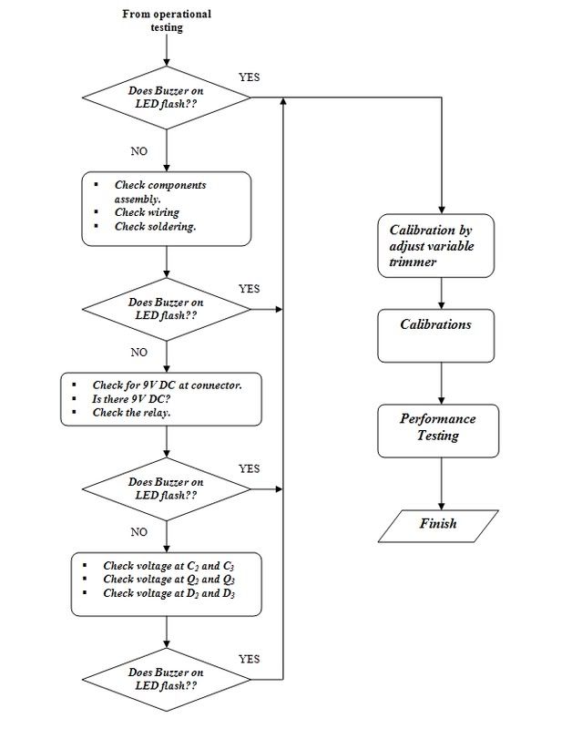
Troubleshooting Results
1. Define the problem.
_______________________________________________________________
_______________________________________________________________
_______________________________________________________________
2. Steps taken to correct the problem.
_______________________________________________________________
_______________________________________________________________
_______________________________________________________________
3. Is project functioning satisfactorily?
Yes ____ No ____ Init. _____ Date _______
Performance Test Results
1. User test performed ______________________________________
_______________________________________________________________
2. User test results. _______________________________________
_______________________________________________________________
Concluding Comments
_______________________________________________________________
_______________________________________________________________
[ 本帖最后由 音魂不散 于 4-5-2007 09:10 AM 编辑 ] |
|
|
|
|
|
|
|
|
|
|
|
楼主 |
发表于 3-5-2007 04:53 PM
|
显示全部楼层
|
Summary and Recommendations Document
Touch Activated Alarm
by
Our goal was to design and fabricate a Touch Activated Alarm prototype project. The goal has been met and the Touch Activated Alarm meets all preliminary project objectives. The initial design has proven valid, and no unanticipated design or fabrication problems developed during prototype construction. It is the recommendation of this technician that full-scale production of the Touch Activated Alarm be given serious consideration.
Name: ___________
Signature: _____________
Date: _____________
[ 本帖最后由 音魂不散 于 4-5-2007 09:12 AM 编辑 ] |
|
|
|
|
|
|
|
|
|
|
|
楼主 |
发表于 3-5-2007 04:58 PM
|
显示全部楼层
WORKING SCHEMATIC DRAWING:
Touch Activated Alarm
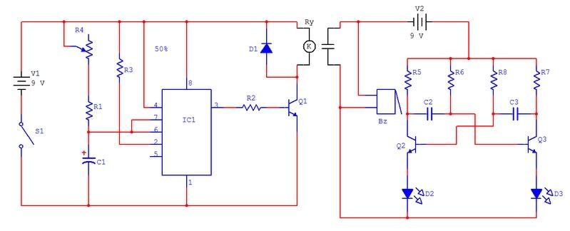
Schematic Drawing Part List:
Touch Activated Alarm
Qty.
| Symbol
| Description
| Part No.
| 3
| R1, R6, R8
| Resistor, 100 kΩ, ¼ W
|
| 1
| R2
| Resistor, 4.7 kΩ, ¼ W
|
| 1
| R3
| Resistor, 10 MΩ, ¼ W
|
| 1
| R4
| Trimmer 100 kΩ
|
| 2
| R5, R7
| Resistor, 470 Ω, ¼ W
|
| 1
| D1
| Diode, 1N4004
|
| 2
| D2, D3
| Diode, LED-Red
|
| 1
| C1
| Capacitor, 47 μf
|
| 2
| C2, C3
| Capacitor, 10 μF
|
| 3
| Q1, Q2, Q3
| Transistor,2N3904
|
| 1
| S1
| Switch
|
| 2
| V1,V2
| 9V DC
|
| 1
| IC1
| 555
|
| 1
| Bz
| Buzzer
|
| 1
| Ry
| Relay 9V
|
|
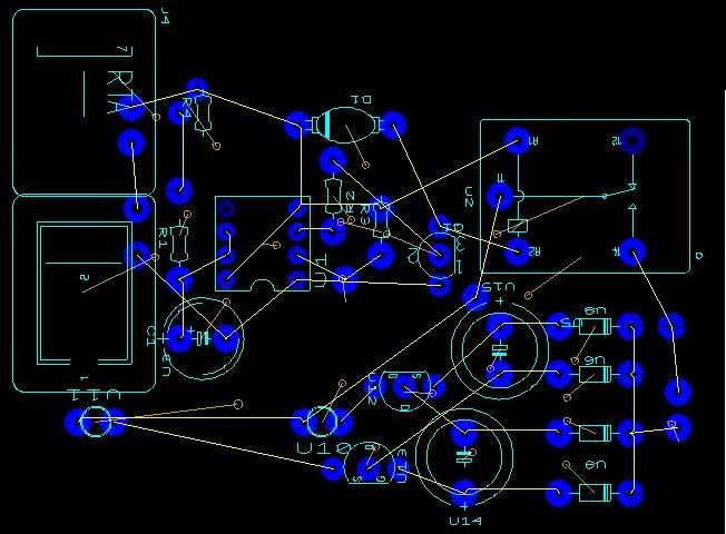
PC BOARD ASSEMBLY DRAWING:
Touch Activated Alarm
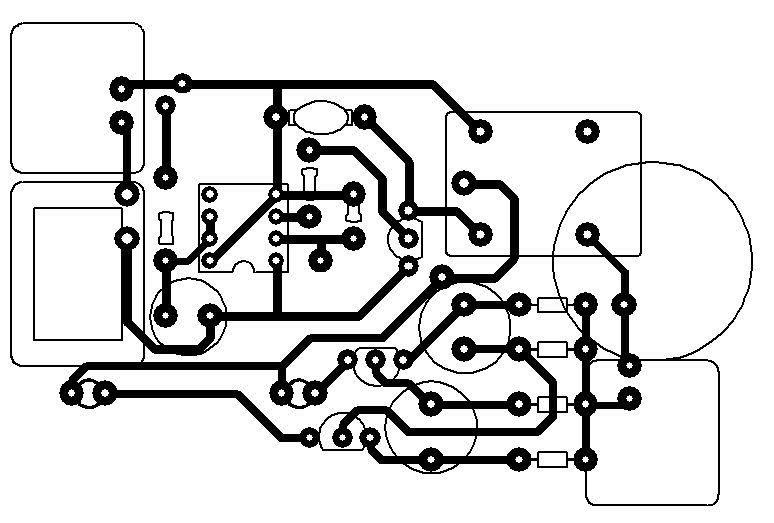
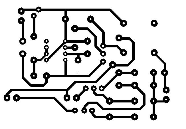
PC BOARD ARTWORK DRAWING:
Touch Activated Alarm
[ 本帖最后由 音魂不散 于 4-5-2007 08:47 AM 编辑 ] |
|
|
|
|
|
|
|
|
|
|
|
楼主 |
发表于 4-5-2007 08:53 AM
|
显示全部楼层
|
|
|
|
|
|
|
|
|
|
|
楼主 |
发表于 4-5-2007 09:01 AM
|
显示全部楼层
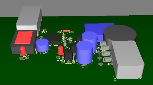
Project终于大工告成了...
在次谢谢大大一路来的帮忙...
还有其他有进来...帮忙解决问题的人..谢谢你们....
成功了...!!
[ 本帖最后由 音魂不散 于 4-5-2007 09:03 AM 编辑 ] |
|
|
|
|
|
|
|
|
|
| |
 本周最热论坛帖子 本周最热论坛帖子
|


 2077
2077  245
245